
PC Power Control with a Raspberry Pi and MAAS

Canonical
on 23 September 2015
Tags: Juju , MAAS , Raspberry Pi
I recently decided to setup a small cluster of computers at home to be managed by Juju and MAAS. The computers are in the attic which meant that finger based power management was going to quickly lose its appeal. Many of my friends and colleagues have enviable home computer setups, with power control being done elegantly by iLO/LOM/Intel AMT or some such. None of my old tin boasted anything as grand as that. I could have used wake-on-lan as both MAAS and my old machines support it but it doesn’t provide a reliable way to power machines off (they don’t always have shell access) or to check their current power state (they may not be on the network). What I’d have loved to do was build a rebot but that would be costly and I’d have to design a bespoke rig for each piece of hardware since my old kit is not in neat NUC form. In the end I decided to get a Raspberry Pi Model B to do the job. Unfortunately, I know next to nothing about electronics and do not own a soldering iron so my solution had to be solder free.
Research
I found this blog (minus tampering with the power feed between power supply and mother board) and this blog (but extended to control multiple machines) both very helpful and they inspired the final design.
The Basic Design
ATX motherboards expose pins that a computer case uses to wire in the reset button, power button and power leds. I removed the connections to the case and instead wired the power and reset pins to relays controlled by the Pi and wired the pins controlling the power led into one of the PiFaces’ Input ports.
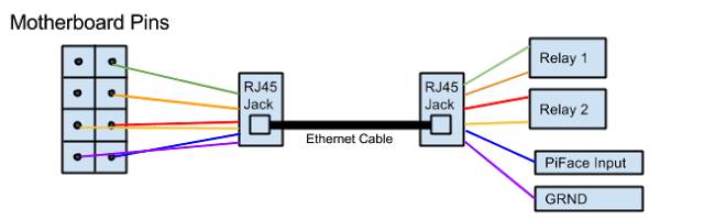
The prototype had jumpers cabled directly from the pins to the Pi but I wanted to be able to unplug the computers from the Pi and have them some distance apart so I used Ethernet cables to connect the Pi to the computers pins. Essentially the solution looks like this…
The Raspberry Pi
I used a Raspberry Pi Model B with a Piface hat. I had the Piface in a drawer so I used that for the prototype as it comes with two relays.
Setting up the Relays
The relays on the Piface worked but I needed two relays per PC. To get more relays I bought an Andoer 5V Active Low 8 Channel Road Relay Module Control Board. Oh, and by the way, one RJ45 jack cost twice as much as the 8 relay Arduino board.
Connecting the relay board to the Pi was straight forward. I attached the ground pin to the Raspberry Pi ground and the 7 remaining pins to the 7 PiFace output pins. The relay also came with a jumper which I put across the VCC-JD and VCC pins for reasons.
At the PC End
The PC part of the puzzle was simple. I used jumper cables with a female end and used them to connect the motherboard pins to a depressingly expensive RJ45 jack. The connections on the RJ45 jack are numbered, below is how I wired them to the motherboard.
| Colour | Green | Orange | Red | Yellow | Blue | Purple |
| ATX Pin | Power | Power | Reset | Reset | LED – | LED + |
| Ethernet Cable Number | 1 | 3 | 6 | 2 | 5 | 4 |
Raspberry Pi End
The ethernet cable from the PC was again terminated with a RJ45 jack whose connections were wired into the Pi as below:
| Colour | Green | Orange | Red | Yellow | Blue | Purple |
| Raspberry Pi Location | Relay 1 | Relay 1 | Relay 2 | Relay 2 | GPIO 1 | Ground |
| Ethernet Cable Number | 1 | 3 | 6 | 2 | 5 | 4 |
Finished Hardware
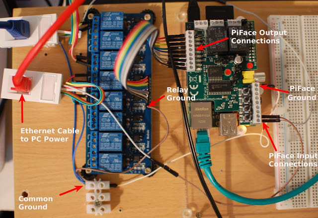
- The breadboard in the picture was used for prototyping but was not used in the final design.
- The colours of the jumpers may not match those in the tables above because some got damaged and were replaced.
- I had problems with the second relay so it was not used.
Software
Once everything was connected, MAAS needs a way to remotely control the relays and to check the state of the input pins. I began by writing a Python library and then adding a REST interface that MAAS could call. Finally I installed gunicorn to run the server.
cd ~

apt-get install -y python-pifacecommon python-pifacedigitalio bzr gunicorn python-yaml

bzr branch lp:~gnuoy/+junk/pimaaspowersudo

cp pimaaspower/pipower /etc/gunicorn.d/

sudo service gunicorn restart
MAAS
MAAS knows about a number of different power management interfaces and it was fairly straight forward to plug a new one in, although because it involves editing files managed by the MAAS package these changes will need reapplying after a package update. I believe that making power types more pluggable in MASS is in the pipeline.
- Firstly add a new template to /etc/maas/templates/power/pipower.template content here.
- Add an entry to JSON_POWER_TYPE_PARAMETERS in /usr/lib/python2.7/dist-packages/provisioningserver/power_schema.py
    {
        'name': 'pipower',
        'description': 'Pipower',
        'fields': [
            make_json_field('node_name', "Node Name"),
            make_json_field('power_address', "Power Address"),
            make_json_field('state_pin', "Power State Pin Number"),
            make_json_field('reset_relay', "Reset Relay Number"),
            make_json_field('power_relay', "Power Relay Number"),
        ],
    }
- Tell maas that this powertype supports querying powerstate (unlike wake-on-lan). Edit /usr/lib/python2.7/dist-packages/provisioningserver/rpc/power.py and add ‘pipower’ to QUERY_POWER_TYPES
- sudo service maas-clusterd restart
- Edit the nodes registered in MAAS

- Power Type: ‘Pipower’.
- Node name: Can be anything but it makes sense to use same node name that MAAS is using as it makes debugging easier.
- Power Address: http://<PIPOWER IP>:8000/power/api/v1.0/computer
- Power state Pin: The number of the PiFace Input port for the power LED
- Reset Relay number: The number of the relay controlling the reset switch
- Power Relay number: The number of the relay controlling the power switch
Scaling
There are eight relays available and each computer to be managed uses two of them so the system will support four machines. However the reset relay is not strictly needed as MAAS never uses it which means you could support eight machines.
End Result
I can now have MAAS provision the machines without me being physically present. So, for example, I can use Juju to fire up a fully functioning Openstack cloud with two commands.
juju bootstrap

juju-deployer -c deploy.yaml trusty-kilo
In the background Juju will request as many physical machines as it needs from MAAS. MAAS with bring those machines online, install Ubuntu and hand them back to Juju. Juju then uses the Openstack charms to install and configure the Openstack services, all while I’m downstairs deciding which biscuit to have with my cup of tea. Whenever I’m finished I can tear down the environment.
juju destroy-environment maas
MAAS will power the machines off and they’ll be put back in the pool ready for the next deployment.
NOTE: I adapted an existing bundle from the Juju Charm store to fit Openstack on my diminutive cluster. The bundle is here.
Ubuntu Desktop for Raspberry Pi
Watch the live event of the 20.10 launch the and find out all the news about the new Ubuntu Desktop image for Raspberry Pi.
Newsletter signup
Related posts
What is a Kubernetes operator?
Kubernetes is the open source, industry-standard platform for deploying, managing and scaling containerized applications – and applications on Kubernetes are...
Operate popular open source on Kubernetes – Attend Operator Day at KubeCon EU 2024
Operate popular open source on Kubernetes – Attend Operator Day at KubeCon EU 2024
Understanding roles in software operators
In today’s blog we take a closer look at roles – the key elements that make up the design pattern – and how they work together to simplify maintaining...